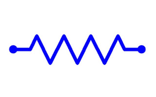
Line Resistance in Transmission Line
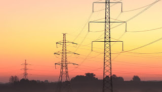
Line Resistance in Transmission Line :- 👉Every electric conductor oppose the flow of current in it ,this is known as resistance. 👉The power loss (I^2R) in the transmission line occurs due to this resistance. 👉The ohmic resistance R of a conductor of length ' l ' and uniform cross sectional area 'a', R= ρl/a Where, R=Total resistance in Transmission Line, ρ=Resistivity or specific resistance of conductor material , l=Length of the conductor, a= Area of cross section, 👉The Resistivity or specific resistance of the conductor is depends not only on the conductor material but also it's temperature. 👉For example ,if ρ₁ and ρ₂ are the values of resistivity at different temperatures t₁ and t₂ ,then ρ₂=ρ₁{1+α(t₂-t₁)} Where, a = Temparature coefficient of resistance of the material. 👉The value of the temparature coefficient of resistance i...